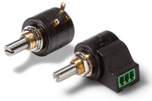
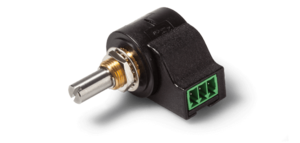
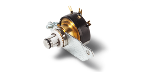
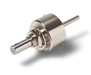
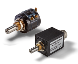
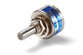
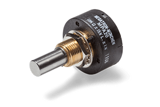
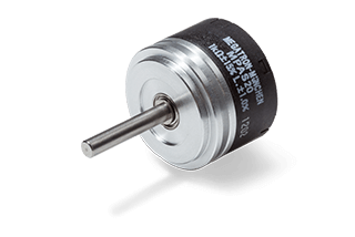
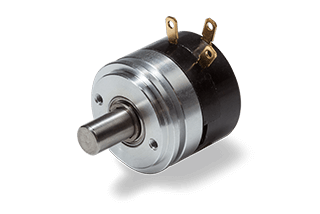
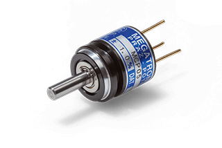
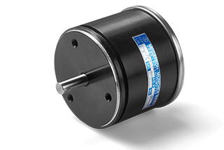
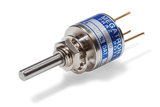
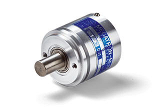
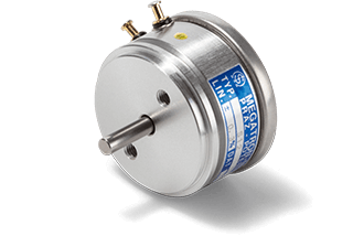
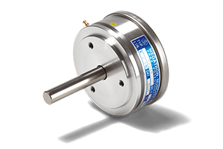
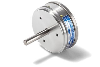
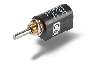
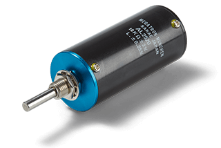
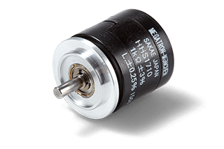
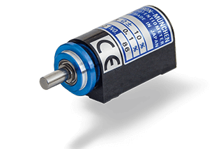
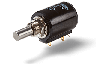
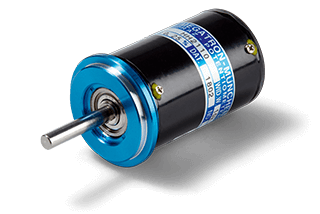
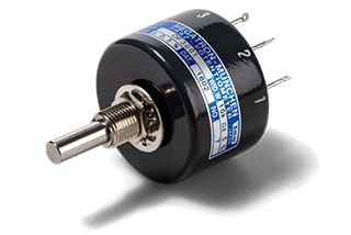
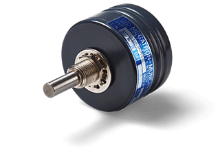
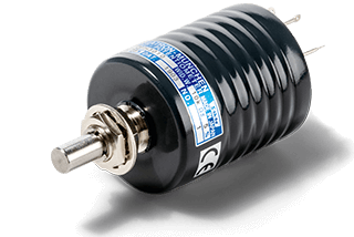
Potentiometers
Conductive Plastic, Wirewound, Multiturn and Tandem Potentiometers
Guide for Potentiometers
Index
- Advantages of potentiometers
- What is a potentiometer?
- Electrical connection and signal output
- How many connections do potentiometers have?
- Potentiometer technologies
- Resistance elements in comparison
- Multigang / Tandem potentiometers
- Oilfilled potentiometers
- Amplifier for potentiometers
- Product customization
- Mechanical optimizations
- Electrical optimizations
What is a potentiometer or pot?
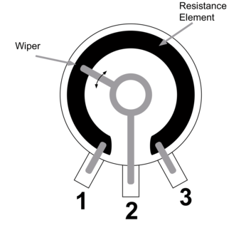
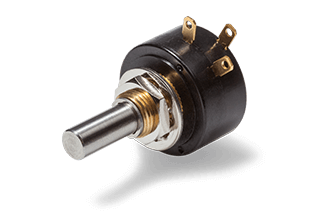
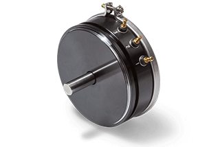
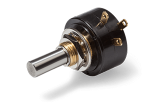
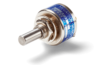
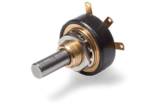
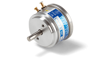
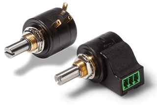
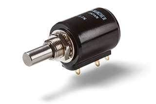
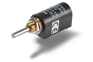
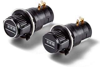
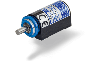
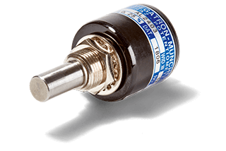
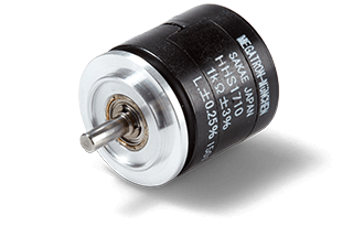
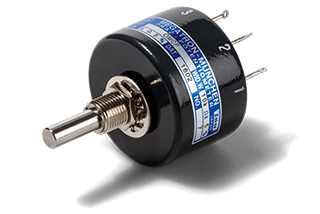
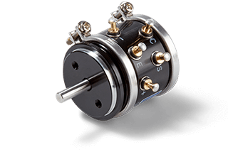
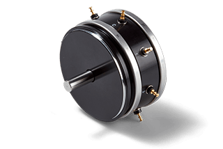
The potentiometer was invented by Johann Christian Poggendorff in 1841. It has been used as an input element and sensor since the beginning of its commercial use in electrical engineering. In principle, the design and function of all "potentiometers" are the same. They have a resistive element with a movable wiper contact that taps a voltage potential on a resistive track. Potentiometers are therefore variable voltage dividers. The resistance element is circular for rotary potentiometers and linear for linear potentiometers. For connection to the application, rotary potentiometers have a mechanical connection (usually a shaft) and electrical connections (usually three).
Advantages of potentiometers
Potentiometers are well established sensors. They are popular because
- they are easy to integrate into the application,
- they have low power consumption and
- the signal is immediately available with no computation time.
In general, potentiometers
- are not suitable for high mechanical shock loads or
- are not suitable for high adjustment speeds >400 rpm
but are considered
- to be insensitive to EMC influences and
- insensitive to ESD influences
as they are passive components.
Above all, they have been tried and tested over a long period of time and their operation is well known. Basically, potentiometers are used wherever angles or positions need to be measured. The large number of potentiometer types and their variants cover a very wide range of applications. Even within a particular potentiometer technology, there is a wide variety of features and options. The suitability of a potentiometer for a particular application therefore depends on the application.
Electrical connection and signal output of potentiometers
Potentiometers usually have three terminals: Two for the resistive element and one for the wiper (signal output). If you follow a standard potentiometer connection diagram and apply 0 V to the defined terminal "one", 5 V to terminal "three" and turn the potentiometer shaft, a voltage signal of 0 to 5 V will be "output" via terminal "two" (on the wiper). An absolute analogue signal is immediately available, without any turn-on delay or calculation time.
The value of the output signal depends on the applied voltage in relation to the position of the wiper on the resistance track. By changing the position by rotating and changing the direction of rotation, a voltage difference between position A and position B can be detected and the position can be determined in angular degrees.
Our potentiometers almost exclusively provide a linear output signal. Exceptions are our sine/cosine potentiometers.

The angular position of rotary potentiometers can be easily determined using the formula below:
\(θ = \frac {Vout} {Vin} * \text{electrically effective angle of rotation}\)
Example: \(θ = \frac {4} {5} * 320° \approx272°\)
If approximately 4 V is measured at the wiper with a total angle of 0° to 340° and a voltage range of 0 to 5 V, this would correspond to an angle of approximately 272°. However, this is a theoretical value as potentiometers have different values of hysteresis and linearity tolerance depending on their design.
How many contacts does a potentiometer have?
Does a potentiometer have two, three or more connections?
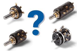
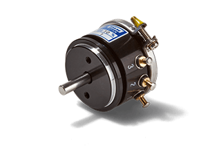
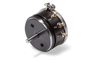
This question can only be answered by looking at the type of potentiometer. In most cases, potentiometers have three connections or contacts. However, if several potentiometers are mounted in series in a single housing, the number of contacts increases. For example, a tandem potentiometer (2 x potentiometers in a row) has six connections / contacts. If the application requires a centre tap for the potentiometer, the number of connections / contacts increases accordingly, usually from three to four.
Non-linear potentiometers (sine / cosine) have five connections: One for positive and one for negative (opposite) voltage and one for ground. To pick up the signal, the potentiometer has two wiper outputs, which pick up the voltage in the potentiometer on the resistance track offset by 90°. This gives a total of five connections / contacts.
There are also components similar to potentiometers, so-called rheostats (adjustable resistors). These usually require only two connections for their switching mode (rheostat circuit). If these components have only two connections, this is an indication that they are not potentiometers but rheostats. However, we do not stock rheostats.
Potentiometer technologies
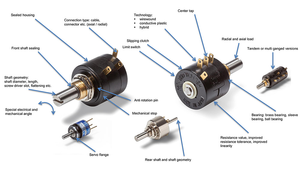
Our precision potentiometers are available in three different resistor technologies. The resistor element is largely responsible for the quality and performance of the application.
- Wirewound potentiometers have a resistive track of wire, usually wound around a ceramic core.
- Conductive plastic potentiometers have a resistive track made of a conductive plastic material.
- Hybrid potentiometers have a resistive track that consists of a combination of a wire and a conductive plastic.
Wirewound potentiometer
- In principle, they can also be used as variable resistors (in a so-called rheostat circuit). However, we recommend the voltage divider circuit, as the components are designed for this purpose.
- Available in so-called single-turn (<360°) and multi-turn (>7200°) versions.
- They have a limited lifespan due to wear and tear and due to the winding jumps of the wire windings "steps" in the output signal, which manifest themselves as noise when the wiper moves.
Conductive plastic and hybrid potentiometer
- Both technologies must never be used as variable resistors (rheostat circuit), but only in a voltage divider circuit
- Conductive plastic is only available as a single-turn version and hybrid is only available as a multi-turn version
- Hybrid potentiometers bring the benefits of conductive plastic potentiometers to multi-turn potentiometers
- They have a significantly longer lifespan because the resistance track is very smooth, they have a theoretically infinite resolution, a very smooth output signal, excellent linearity and allow higher adjustment speeds.
Resistance elements in comparison
| Resistive element | Conductive Plastic | Wirewound | Hybrid |
| Lifespan | ++ | 0 | + |
| Signal quality / resolution | +++ | + | +++ |
| Linearity | +++ | +++ | ++ |
| Electrical travel | max. 360° | 10800° | max. 3600° |
| Operational speed | ++ | - | + |
| Max. wiper current | -- | + | -- |
| Shock / Vibration | - | -- | -- |
Legend: +++ best | ++ very good | + good | 0 OK | - low | -- unfavourable | --- not appropriate
Multiganged / Tandem Potentiometer
When redundancy of sensors is required in an application, so-called multiganged potentiometers or tandem potentiometers in a double version are often used. An overview of all multiganged potentiometers can be found here.
Potentiometers are used in applications ranging from mechanical engineering to aerospace. In order to maintain the tight linearity tolerances of the potentiometers, it is important to ensure that the heat generated during operation does not have a negative effect on the properties of the potentiometer due to the adjacent construction. It is therefore necessary to reduce the nominal load according to the table.

These specifications are valid under standard conditions (+15 °C to +35 °C). If the potentiometers are used at higher temperatures, the load must be reduced.
Multiganged Potentiometer AL17/19
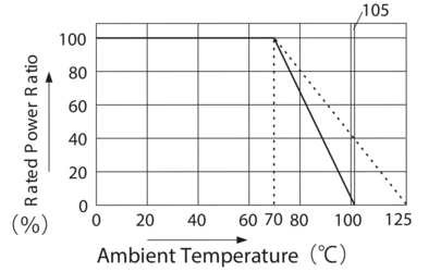
*This graph does not apply to the oil-filled potentiometers.
Oil-filled potentiometers
Oil-filled potentiometers are typically used in special environments where aggressive gases, corrosive salts or moisture may be a problem. These potentiometers are also characterized by the fact that
- that the contact resistance of the wiper is particularly stable over the entire lifespan, as the oil filling suppresses corrosion at or near the wiper.
Some applications for these potentiometers include control systems in areas such as shipbuilding, coastal electrical installations, pits and mines, ironworks, chemical plants, unmanned underground installations and machine tools. However, some applications may require additional approvals, such as explosion protection, which must be obtained separately for each application. Click here to view all oil-filled potentiometers.
OF50 - oil-filled
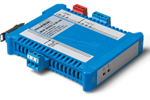
Amplifier / signal converter for potentiometers
As passive components, potentiometers do not offer standardized output levels such as 0..10 V, 4..20 mA. Please note
- that the output signal of the potentiometers should be tapped by means of a voltage divider circuit
- and thus virtually no current flows via the output.
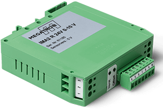
It is therefore not necessary to use the signal itself as a voltage or current source for a converter. To generate standardized signals in a simple design, we offer instrumentation amplifiers that provide standardized signals from an external power supply.
Circuit types
Voltage divider circuit
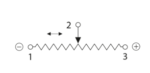
Operate the potentiometer in the voltage divider circuit and limit the wiper current to a minimum. Only in this way will the potentiometer maintain its optimum life characteristics and signal quality
- The tolerance of the total resistance is not relevant
- Temperature effects are almost completely suppressed
The voltage divider circuit offers the advantage of high robustness against parasitic resistances between the resistive element and the wiper. Only the voltage divider circuit allows you to take full advantage of the special design features of each type of potentiometer depending on the application.
Rheostat circuit
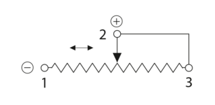
Do not use the potentiometer in a two-wire circuit, as a variable resistor or as a rheostat. This type of circuit has considerable disadvantages in terms of
- signal quality and potentiometer life,
- and is only possible for wirewound potentiometers (at low load).
- Conductive plastic and hybrid potentiometers will be damaged in this type of circuit!
Total resistance
A high total resistance is advantageous in applications where low power is required. A low total resistance is advantageous in applications where "optimum" signal quality is required.
- 500k potentiometer - for very low power applications
- 100k potentiometer - often for battery powered applications
- 10k potentiometer - standard applications
Center Tap
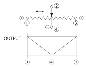
This option allows the use of an additional tap on the resistive track, in the form of a centre tap with half the resistance value corresponding to 50% of the electrical angle of rotation. This makes it possible, for example, to operate the potentiometer bipolar, i.e. with positive and negative voltages applied to the resistive element terminals (terminals 1 and 3), while the centre tap is connected to ground. The centre tap is used in applications where the voltage value at the centre position of the potentiometer must remain the same throughout the life of the potentiometer, or where the output value must be divided into two ranges. Note that there are two possible implementations of this tap.
Voltage tap and current tap

Voltage tap
The voltage tap cannot carry a load. Therefore, no current should flow through the centre tap, otherwise the component will be destroyed.
The following applies to the circuitry of the voltage tap: If the centre tap is connected to ground and the end taps are both negative and positive, currents should be prevented from flowing across the centre tap by connecting an op amp.
If only voltage of one polarity is applied from one end to the tap connected to ground, too much current will flow at the intermediate tap. In this case, the voltage applied between terminals 1 and 3 must in any case be reduced below 50% of the rated voltage (less than 10% is recommended).
Current tap
The current tap will affect the linearity of the component to some extent. Please contact us directly for more information on sensor characteristics in relation to this particular connection.
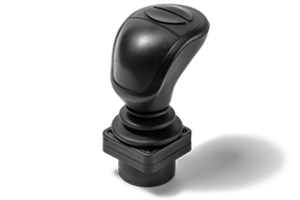
Joysticks are an example application for current taps: For a voltage range of 0 to 5V within the travel range, the centre tap is 2.5V, corresponding to no actuation. Even if certain areas of the resistor track are worn, the value at the centre tap will always be 2.5V and no "wrong" output signals will be generated. Current taps are used throughout, as it is expected that some current will flow through the centre tap.
Environmental influences
Effects of vibration and shock
It is generally recommended to avoid the effects of vibration and shock on potentiometers. Depending on the strength and frequency of these influences, the wiper can "lift off" the resistance track, resulting in signal loss at these moments. In addition, these influences lead to increased wear on the resistance track, resulting in loss of signal quality and reduced lifetime. Wirewound potentiometers are slightly more robust and more suitable for low frequency applications than conductive plastic potentiometers.
Temperature influences
Our potentiometers are specified under standard conditions at room temperature (+15 °C to +35 °C). Lower or higher temperatures can affect signal quality, for example by freezing moisture in the air or evaporating grease on the resistance track. Temperature also affects the operating torque.
The use of appropriate seals or special greases can help. We will be pleased to assist you with the appropriate requirements for your application.
EMC/ESD compatibility
Potentiometers are analogue, "passive" components that contain no electronics to limit their EMC or ESD properties. Potentiometers are therefore considered to be insensitive to electromagnetic interference, which is a great advantage in critical applications.
IP protection class
Almost all our potentiometers are specified to IP40 and almost all can be upgraded to IP65 with a shaft seal. If a higher degree of protection is required, e.g. for the housing, the MFP500 and AL17IP (OFH, OF5001, OF30, OF50)meet this requirement. Options are available for many potentiometer ranges to provide a sealed housing.
First Digit: Solid particle protection
| IP | Degree of protection |
| 0 | Non-protected |
| 1 | ≥ 50 mm |
| 2 | ≥ 12.5 mm |
| 3 | ≥ 2.5 mm |
| 4 | ≥ 1 mm |
| 5 | Dust |
| 6 | Dust-tight |
Second Digit: Liquid ingress protection
| IP | Degree of protection |
| 0 | Non-protected |
| 1 | dripping waters |
| 2 | dripping water when tilted at 15° |
| 3 | spraying water |
| 4 | splashing of water |
| 5 | water jets |
| 6 | powerful water jets |
| 7 | immersion, up to 1 meter depth |
| 8 | immersion, up to 1 meter or more depth |
Shaft torque
Our potentiometers are offered with either precision ball bearings or sleeve bearings. In general, potentiometers with precision ball bearings have a lower torque than potentiometers with sleeve bearings. Servo flange potentiometers are always fitted with ball bearings. For almost all potentiometers it is possible to change the operating torque (e.g. 2 to 3 Ncm at room temperature). In addition to providing a smoother feel, the increased rotational resistance prevents unintentional adjustment due to machine vibration. A wide range of pre-assembled kits and knobs are available to suit your application. See rotary potentiometers
Mechanical stops & slipping clutch
Mechanical stops
In most cases, the mechanical end stop is used for manual setpoint applications. Please note the maximum allowable end stop torque and that all multi-turn potentiometers have a mechanical end stop.
Potentiometers without a mechanical stop will have a voltage fluctuation when the ends are overturned. Do not use the output signals of this end range as useful signals.
Slipping clutch
Slipping clutches are used with our multiturn potentiometers. The main purpose of the slipping clutch is to protect the mechanical stop from damage. However, if the clutch is constantly stressed, it may wear more quickly and its life will be shortened. Please consider this effect.
Operating notes
Applications with very rare actuations
As the saying goes, "rest is rust", and the slider behaves in relation to the resistance track. Oxide/sulphide deposits may form. Please contact us in advance to take appropriate countermeasures. For example, increased contact pressure on the slider or appropriate seals may help.
Applications with very short continuous actuations
Please note that if the stroke is always the same and very short, the resistance element will be subject to increased wear at this point and the life will be reduced. At the same time, microscopic deposits will form on the resistor at the ends of the stroke, affecting the signal quality. Periodic passing over these points can clean the resistance track.
Shaft load & tightening torques
Tightening torques for threads and screws
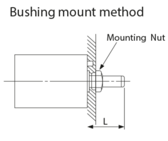
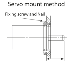
Please note the tightening torques and dimensions for threads and screws to avoid damage to the potentiometer. Particularly for potentiometers with a bushing, the torque on the shaft can be increased if incorrectly fitted. The servo flange potentiometers are supplied with synchro clamps for mounting.
Mechanical coupling
Do not subject the shaft to excessive axial and radial loads over a long period of time. Normally, values of < 1 N are not a problem. Some potentiometers have a reinforced shaft bearing and allow values < 4 N (e.g. ALI17/19). Use a shaft coupling to minimize any shear loads (axial and radial).
When fitting additional components such as shaft couplings, gears, etc., ensure that the shaft is not subjected to permanent loads in excess of 10 N. Short-term loads of this magnitude are not a problem.
Adjustment, mounting types and soldering instructions
Zero point adjustment
A screwdriver slot on the shaft makes it easy to set the zero point. The possibility of integrating a screwdriver slot on the shaft is available for all series with shaft and is already implemented as standard for some of them. Potentiometers with servo flange can be zeroed by simply turning the potentiometer housing. To do this, the synchro clamps must first be loosened.
Soldering note
Use a soldering iron with max. 60 W (<350 °C) for soldering the connections and do not contact with them more than three seconds.
Installation types
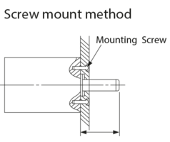
For panel mounting, the potentiometer with shaft must be mounted in a precisely machined hole without backlash. For potentiometers with a fixing pin, the so-called anti-rotation pin, a corresponding hole must be provided.
For hollow shaft potentiometers, rigid mounting of the housing must be avoided. This is because the hollow shaft is not suitable for bearing the actuating shaft.
The depths and diameters given in the data sheet for potentiometer body sizes do not take into account the dimensions of the electrical connections. If space is limited, consider the orientation of the connections and the additional space required.
Frequency Effect
Use in high frequency technology
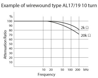
Due to the mechanical construction, especially of multiturn potentiometers (wire winding), potentiometers have different values of inductance and capacitance, which must be taken into account in high frequency circuits. These characteristics lead to phase shifts between current and voltage, as well as damping effects. However, in wirewound potentiometers (including hybrid potentiometers) these effects typically only occur at frequencies above 20 kHz. With conductive plastic potentiometers, these effects are negligible up to about 200 kHz, as there is no winding.
Hysteresis / Backlash
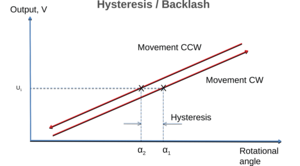
If the slider is moved in one direction over the resistance path, a certain electrical value (U1) is reached at a certain point (α1). If the slider is moved in the opposite direction, the same electrical value is reached at a different point (at a different angle, α2). This difference is expressed in angular degrees and is called hysteresis or backlash.
Hysteresis thus describes certain effects on the accuracy of measurements. Due to this effect, the output signal can be assigned to two different angular values depending on the direction of the wiper.
Linearity
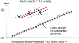
Linearity expresses the deviation of the output voltage curve from the theoretical ideal curve. Typically, potentiometers are specified with independent linearity, which does not require the straight line to pass through zero. To determine this, an optimum straight line is drawn through the actual output voltage curve so that the deviations of the curve from the straight line are minimized. The distances (delta) in the figure represent the specified independent linearity, given as a percentage.
The lower the linearity value, the smaller the deviations from the correct measured value can be expected.
Product customizations and options
For over 60 years MEGATRON has been a reliable partner for your design-in. In addition to the wide range of options available for our sensors, we also offer specific designs to meet your application requirements, even in small quantities. Whether it is a prototype project or series production, we are here to help.
The boundaries between standard and non-standard items are blurred. The sheer number of options makes it virtually impossible to present every possible electrical and mechanical combination, or even to stock them as physical items. Even for a relatively simple potentiometer, the variety of articles would be xn (several hundred to a thousand variants). For this reason, we have highlighted in the datasheet those product options that have a high level of market acceptance and declared them as standard.
The choice of options often involves electrical or mechanical modifications to a product. In addition, we can provide product adaptations that go beyond the options in the order code and give examples of further possibilities. It is our ability to optimize the product to meet the requirements of the application that sets us apart.
That is why it is important for us to understand the application and the field of use as well as possible. In this way, we can determine the technical possibilities and economic implementation of the product you are looking for, while at the same time examining our entire product portfolio. As part of our consultation, we will identify the item that meets your requirements and, if necessary, suggest alternative products if they offer you advantages in terms of economy and technology.
Mechanical optimizations and beyond
Assembly of cables and connectors
Please define your application requirements in terms of environmental conditions and installation situation - if required, we will take care of the operational implementation such as sourcing and assembling cables and connectors for the item offered. All from one source - saving you time and money.
Mounting of mechanical components
Optimization of the shaft
In our datasheets we list the possibilities of adapting the potentiometer shaft to your application: Whether it is the shaft diameter, the shaft geometry or a continuous shaft, also with the possibility of adapting the diameter to the geometry. In addition, we make adjustments to the bushing for optimum connection to the application.
Torque optimization
In principle it is possible to adjust the torque for all potentiometers. We use special lubricants with the appropriate viscosity to suit the application and environmental conditions. For example, in applications where a sensitive change in position is required, sensors with a comparatively low actuating torque are used. Where an unintentional setpoint change due to incorrect operation is to be prevented from causing damage to the machine or injury to persons, potentiometers with a higher torque are used.
Increasing the IP protection
Depending on the environment, it is often necessary to increase the IP protection of the potentiometer. We offer sealing elements for the shaft to protect against moisture and dust, as well as sealing elements between the panel and the sensor. It is also possible to seal the housing. In many cases potting of the housing is required, but fully potted potentiometers are also available. Please contact us with your requirements.
Electrical optimizations
Optimization of the electrical and/or mechanical angle of rotation

We offer a very wide and deep range of potentiometers. However, some applications require adjustment of the mechanical angle of rotation by means of end stops and/or the electrical angle of rotation by means of limiting the output curve, so that the potentiometer best meets the requirements.
Optimization of linearity and resistance values
For demanding applications, we can optimize the linearity and/or resistance values in addition to those already listed on the datasheet. Our potentiometers are manufactured in a highly tempered production process. We are therefore able to meet these requirements as far as technically possible.
Not all potentiometers are alike! Our range includes only potentiometers with much tighter electrical and mechanical tolerances, significantly longer life, higher reliability and better component quality than conventional low-cost potentiometers: Namely precision potentiometers; and this for over 60 years.
Our extensive range of potentiometers is based on a wide variety of applications. However, it is not sufficient for all applications. In many cases, demanding applications require technical customization, which we can provide even for relatively small quantities.
As part of our consultancy service, we work with you to define the optimum product for your 'design in'. Our aim is to provide each customer with the best functional and economic result. With high delivery reliability and assured product quality, we focus on long-term partnerships and support you throughout the life of your application.
 EN
EN DE
DE ES
ES FR
FR IT
IT
