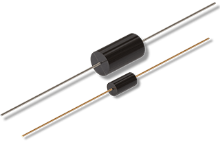
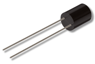
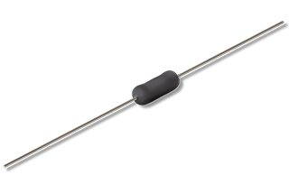
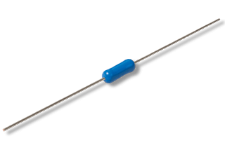
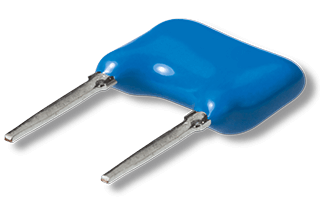
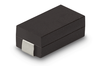
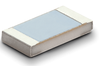
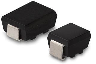
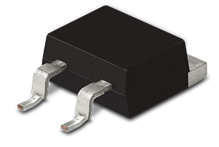
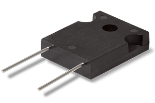
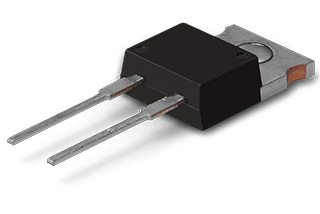
Resistors
Power, precision and SMD resistors
Guide for Resistors
Index
Who discovered it?
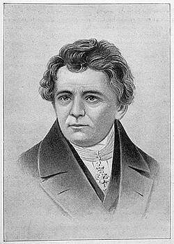
Georg Simon Ohm, German physicist. Date: 1789 - 1854
Even the first experimenters in the "primeval times" of electrical engineering knew that a certain "factor" was always involved in their experiments, which limited the "effect of flowing electricity". However, it was not possible to measure any of the important electrical quantities (today called "electrical current", "electrical voltage") exactly and to understand this relationship conclusively. It was Georg Simon Ohm (1789-1854) who developed a fundamental theory from his research on electricity, whose formulae are still widely used today. Now the basis had been laid for understanding the relationships between these quantities: Resistance simply occurs as the relationship between voltage and current. Finally, resistance values could be calculated and the production of components with defined resistance values became possible. This has led to an unbelievably large number of resistor designs based on various resistor technologies.
What is a resistor?
In a fundamental sense, electrical resistance is a quantity that describes the current that a current-carrying material allows at a specified voltage. The physical reason for this effect can be explained in this way: Free charge carriers (electrons) are prevented by impacts on atoms from being freely accelerated in the conductor. The word resistor is derived from the Latin "resistere" for to resist, which describes the physical effect quite well.
The value of the resistor is given in Ohm (Ω), the circuit symbol is either an "empty rectangle" according to EN60617 or has the shape of a zigzag according to ANSI.

Circuit symbol for an electrical resistance: rectangle according to EN 60617 or "zigzag" according to ANSI
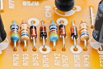
An electrical resistance in the sense of an electronic component is used to limit, measure, divide electrical currents and much more. In principle, the material used, as well as the thickness and length of the resistor element determine the current flow for all resistors. The simplest electrical resistance can therefore be a piece of wire, although its resistance value is negligible and can usually be neglected when calculating a circuit.
Simply described, the resistance value of an electrical conductor is determined by dividing the electrical voltage by the current:
R = U / I (R...resistance; U... voltage; I...current)
Ideally the resistance value is constant. So it does not change its value depending on the current or voltage applied:
R = U / I = const.
Then it is also called "Ohmic" resistance and the relation is known as Ohm's law. In practice, this is usually taken for granted when calculating circuits.
Unfortunately, however, in reality there are influences that change the resistance value. But it is mainly the temperature that has a certain influence on the value even at the best resistors, because materials change their behaviour when temperature changes. For this see below the explanation of the TC-value. In addition, there are noise effects, which also make the treatment of electrical circuits more difficult (see noise behaviour of resistors). Last but not least, ageing influences occur and this is where the wheat separates from the chaff.
Noise behaviour of resistors
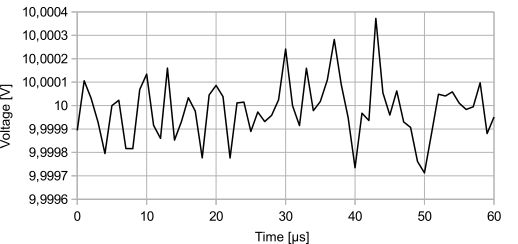
Thermal noise in the sub-mV range with a signal of exactly 10 V
There are basically two types of noise sources when operating resistors:
- thermal noise and
- current noise
Thermal noise / white noise
Thermal noise is a fundamental physical effect that occurs even in an idealized, "theoretical" component. It is also known as "white noise". The effect becomes stronger as the temperature increases, and it is therefore recommended that the temperature be kept as low as possible to minimize this noise component. The noise is also not dependent on frequency when operating on AC voltage. The white noise occurs independently of an applied voltage and the noise voltage can be calculated or estimated as follows:
\(U_R = \sqrt(4 * k_b * (T_c+273.15) *∆f\)
kb = 1.38*10-23 (Boltzmann constant)
TC = temperature in °C
R = resistance value
∆f = bandwidth in Hz (frequency range under consideration)
For a value of R = 1 MΩ, a bandwidth of ∆f = 20 kHz (range of the human ear) results in a noise voltage of about 0.018 mV or 18 µV.
This value is not large, but can be a problem in applications where very small signals are to be measured. Especially in audio technology, this noise is the constant companion of developers of high-quality devices, because basically everything that is electrically conductive generates noise.
Current noise
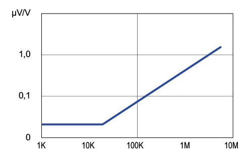
Current noise of a precision resistor series NC550
Unlike white noise, current noise only occurs when a voltage is actually applied to a resistor. The current flowing in the element (the desired current) is overlaid by the current noise. The cause of the effect, however, lies precisely in the desired current, so there is a dependence on the value of the desired current itself. Here the behaviour of the element depends very much on the resistor material used. The unit for the current noise is usually specified in µV/V (typically as maximum value). This means that this value can simply be multiplied by the voltage, resulting in the (maximum) noise level that can be expected. The values depend on the resistance value itself and usually get higher at higher resistance values.
Load capacity and power loss of resistors

Power derating curve of a precision resistor series NC550
Resistors generate power loss by converting electrical energy into thermal energy. This heat must be dissipated so that the component does not overheat. The maximum temperatures are specified on the data sheets. For more sophisticated models, graphs showing the dependence of maximum power on temperature, the power derating curve, can be found. If the maximum allowable temperature is exceeded, the component will suffer damage and may either fail completely or its properties may deteriorate or change. For resistors that can take a particularly large amount of power, the data sheet contains information on how the heat dissipation must be carried out. In some cases there are heat sinks that require not only convection and radiation but also the dissipation of heat via contact to a larger heat sink. Depending on the installation situation, the specifications may differ or the installation recommendations may be mentioned for the different situations. The power loss of resistors, i.e. the power that is converted into heat, is calculated for direct current with
P (power) = U (voltage) *I (current).
For alternating current, RMS values of current and voltage are used. It is expressly recommended not to go too close to the specified performance limits when selecting the component. A resistor operated at the limit will become hot and will then also heat up the environment, which can have side effects on other components. These side effects can lead to the fact that a circuit precisely designed with high-quality components can lose the entire advantage of precision due to these heat effects, which leads the project ad absurdum. In addition, one has hardly any reserves in case something goes "wrong" and the load becomes higher than initially calculated. It can sometimes be useful to connect two power resistors in parallel to avoid the use of a single more powerful and usually more expensive resistor. If on data sheets the temperature is related to the ambient air, then the temperature which actually flows around the component (ideally cooling air) should be used as reference instead of the room temperature around the device. Here the value can be much higher. If the need for higher performance should nevertheless have to be met, there are models that can help: Some resistor models allow pulsed operation at a much higher load for a short time. See the guide for power resistors.

Ageing and stability behaviour
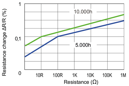
Stability plot of a precision resistor at a power of 70 Watt
Basically, electrical resistors change their resistance value over their lifespan without external influences. Here, especially at the beginning of the lifespan, there can be stronger changes than later in operation. Therefore, it is obvious to artificially age the resistor in an accelerated process in case of special stability requirements. The term "stability" is generally used in this context. In the case of precision resistors, data sheets usually contain graphs showing the change in resistance at constant (specified) power as a function of the resistance value and operating time.
Resistors change their values when the temperature changes. This dependence of the total value on the temperature depends strongly on the design and the material used. In addition, the operation of the resistor itself generates heat. In order to minimize this effect, sufficient ventilation must therefore be ensured. In addition, it is recommended not to operate the components close to the maximum allowable power dissipation, because especially in this case a lot of heat generation by the component itself can be expected.
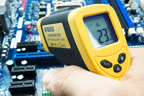
The temperature coefficient (so-called TK value) is given as a measure of the change in resistance value. The value is specified in units of ppm / ˚C (ppm = parts per million, 1 ppm = "1 millionth" of the total value).
If a TC value of ±50 ppm / °C is specified for a resistor, then the resistor changes at a temperature change of 1°C by a maximum of the multiplicative factor ±0.000050, i.e. by "50 millionths" of the total value. Assume that a component has a specified resistance value of 1 MΩ. Then, if the temperature increases and decreases by 1°C, the resistance value can change according to the specification by up to 50 Ω, i.e. by up to 50 Ω smaller or larger. In general the following formula can be used:
RT=Rref *[1+TK*(T-Tref)]
Whereby
Tref... reference temperature (usually 20°C, sometimes also 0°C or 25°C)
Rref...reference resistance
TK...temperature coefficient
T... operating temperature
RT...resistance value in operation
This applies to the example in the text above:
Tref = 20°C
Rref = 1 MΩ = 1 000 000 Ω
TK = ±50 ppm / °C = ±0.000050 / °C
The formula for gives the following values for the changes of 1°C and 10°C
R(T=20°C) = 1 MΩ * [1 ± 0.000050 * (20 - 20)] = 1 MΩ * [1 ± 0] = 1 MΩ
R(T=21°C) = 1 MΩ * [1 ± 0,000050 * (21 - 20)] = 1 Ω * [1 ± 0,000050] = 1 000 000 Ω ± 50 Ω
R(T=40°C) = 1 Ω * [1 ± 0.000050 * (40 - 20)] = 1 MΩ * [1 ± 0.001000] = 1 000 000 Ω ± 1000 MΩ
We only offer quality resistors that have excellent long-term stability, much tighter resistance tolerances and more precise resistance values than standard resistors. We focus on precision resistors.
Power resistors, precision resistors, voltage dividers or thermistors are often very individual and customized components. With our "Resistor Engineering" we help to find the specific technologies and the optimum product solution, even for relatively small quantities.
We are your partner for assured quality products. With high delivery reliability, we focus on long-term partnerships and support you throughout the entire lifecycle of your application. Our aim is to provide each customer with the best functional and economic result. A complete package tailored to your needs. This has been our motto for over 60 years.
 EN
EN DE
DE ES
ES FR
FR IT
IT
