LVDT Position Sensors
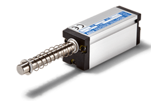
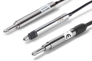
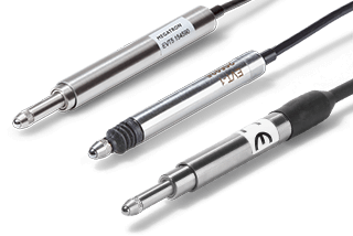
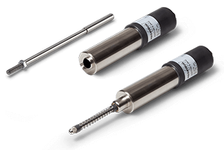
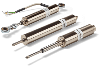
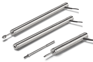
Inductive displacement transducers with probe, spring return, ball joints or loose core
Guide LVDT position sensors
Index
Basic questions about linear sensors? Here you will find the answers
Inductive linear measuring principle
The measured value acquisition is contactless. Our range includes only LVDT displacement transducers. For the sake of completeness, we distinguish between two types of inductive displacement sensors:
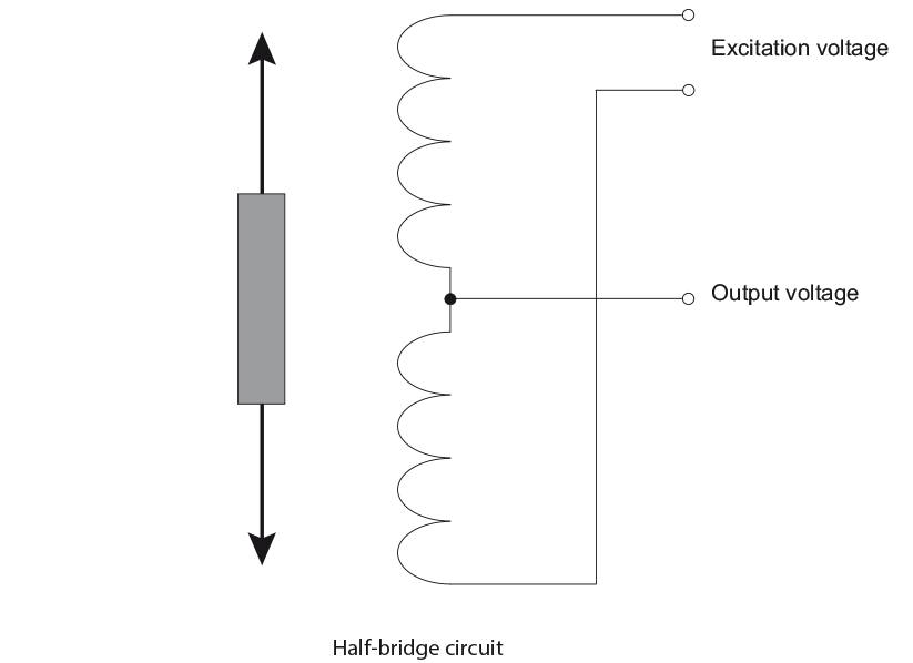
Half bridge circuit
(differential throttle principle)
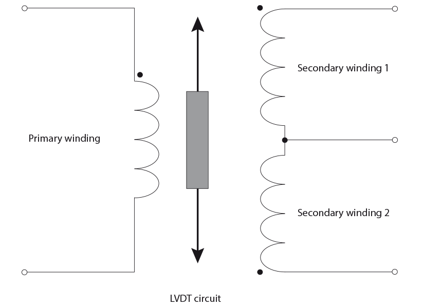
LVDT circuit
(Linear Variable Differential Transformer)
An LVDT transducer consists of a corrosion protected, magnetically shielded hollow body, a primary coil (primary winding), two secondary coils (secondary windings) arranged in series, and a push rod with a soft iron core (high permeability iron-nickel alloy) at the end. The push rod can be moved axially in the hollow body over the coils without contact and uses the inductive measuring principle as Linear Variable Differential Transformer: LVDT
The primary winding is supplied with an alternating voltage (also known as excitation voltage or primary voltage), usually at a constant frequency in the range 1...10kHz. This AC voltage is induced in the secondary coils into the two secondary windings, depending on the position of the soft iron core, with the secondary coils connected in series in antiphase.
LVDT has the advantage over the half-bridge circuit that the LVDT coils are wound in such a way that mechanical length changes of the coils, caused by temperature changes, are largely compensated.
If the soft iron core is positioned exactly in the centre between the secondary coils, the output voltage is 0 V because the magnetic fields in the secondary coils neutralize each other. If the soft iron core is moved axially, the induced voltages change depending on the direction: the voltage in one secondary coil increases steadily, while it decreases in the other secondary coil.
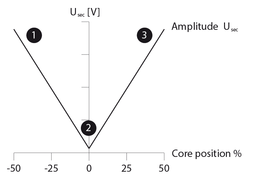
State 1: Move the soft iron core to the right so that the coupling is uneven and the voltage increases. (1)
State 2: When the soft iron core is in the centre of the two secondary coils, the output voltage is 0 V (2) because the magnetic fields in the two secondary coils cancel each other out.
State 3: Move the soft iron core to the left so that the coupling is unequal and the voltage increases. (3)
The output signal results according to the circuit as the difference between these two voltages. This means that the output signal drops / rises to the middle position when the core moves, depending on the direction, and rises / drops again with a phase shift of 180° when the core continues to move.
Advantages of LVDT sensors
- Small measuring paths very well realizable
- Wear and maintenance-free
- Absolute measuring principle - no offset
- Very well suited for oscillating movements
- Suitable for very high temperatures
- Largely insensitive to temperature changes thanks to LVDT technology
- Pressure tight versions for high atmospheric pressure
- Suitable for high adjustment speeds
- EMC-resistant with suitable material selection
Signal, amplifier, protocol
An LVDT is a differential transformer that is supplied with an alternating voltage (AC) and also generates an alternating voltage (AC) as an output signal.
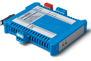
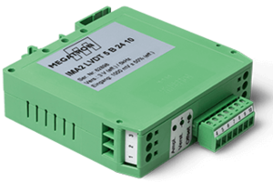
To provide a versatile output signal, inductive displacement transducers are available with suitable processing electronics such as the IMA2LVDT or with integrated amplifier electronics. The latter consists of an oscillator to generate the excitation voltage, a demodulator and differential builder, and an output amplifier with filter. Different output voltage ranges are available, allowing the transducers to be easily adapted to a wide range of measurement and control equipment.
The ratio of the voltages is differentially evaluated by the electronics and usually converted into a standardized output signal (0...10 V, 4...20 mA, etc.). Within the specified measuring range, LVDT sensors have a very good linearity.
Supply voltage - Output voltage: For inductive systems with an external amplifier module, an input voltage of 10 VRMS between 500 Hz - 5 kHz is required. DC-DC types are usually specified at ±15 Volt or 24 VDC.
However, if, as in the case of a potentiometric transducer, a DC voltage supply and processing electronics for DC voltage measurement signals are available, an inductive transducer can be equipped with DC electronics which generate the AC voltage internally in the transducer (oscillator) and convert the measurement signal back to a DC voltage (demodulator), as shown schematically in Diagram 2. In this way, the DG transducer is simply supplied with ±15V or 24V DC and provides 0…5 V / ±5 V / 0…10 V / ±10 V / 0…20 mA / 4…20 mA as a measured output value.
The measurement certificate with all the necessary data on linearity, tolerance, sensitivity, etc. is included.
Inductive linear sensors are robust, absolute measuring systems with a resolution of up to 20 µm. They are suitable for applications with small strokes and especially where oscillating movements with high dynamics or high accelerations need to be detected. Applications requiring pressure tight versions up to 30 bar can also be realized.
Our LVDT linear sensors detect mechanical displacement from 1.3 mm to 940 mm. In addition, the life of the sensor is unlimited because the measured values are recorded without contact. For a variety of applications, variants are available as probes with spring return, with loose core or ball joints to compensate lateral misalignment.
Despite the wide range of available variants, some demanding applications require customized sensor adaptation. MEGATRON is your partner for this adaptation process. For the implementation of special measuring tasks, our many years of experience and broad application know-how are available to you for optimum design-in, even for relatively small quantities.
 EN
EN DE
DE ES
ES FR
FR IT
IT
